Dog Clutch
Clutch with toothed plates that engage when plate teeth become enmeshed

Libraries:
Simscape /
Driveline /
Clutches
Description
The Dog Clutch block represents a nonslip clutch that uses the positive engagement of interlocking teeth to transfer torque between drive shafts. Dog clutches are common in applications that require high-speed and frequent gear shifts. Dog clutches are typical for motorcycle manual transmissions, and some industrial machinery.
The ring and hub are the primary components of a dog clutch. The input shaft turns the ring, which has slots or teeth. The hub connects to an output shaft that has protruding "dogs" that fit into the slots of the ring. When you shift the transmission,the dogs and slots engage and lock the two components and transmitting power. You shift again to disengage the clutch, which causes the dogs to disengage from the slots and allows the transmission to spin freely. The ring and the hub spin together as a unit.
To control engagement, the dog clutch contains a shift linkage that governs the position of the ring with respect to the hub. You can choose to control the shift linkage with a physical signal or a mechanical translational conserving port by using the Torque transmission model parameter. Choose the parameter setting according to your performance, fidelity, and the clutch behavior:
Two-mode— Fully abstracted torque transmission model based on mode charts. This setting is fast enough for real-time simulation and does not require knowledge of the clutch dimensions. You can control the shift linkage only with a physical or logic-controlled signal.Friction clutch approximation - Suitable for HIL and linearization— Medium- to high-fidelity composite implementation of the Fundamental Friction Clutch block. This setting supports thermal modeling. You can control the shift linkage with either a physical signal or a mechanical translational conserving port.Dynamic with backlash— High-fidelity clutch engagement model that accounts for phenomena such as backlash, torsional compliance, and contact forces between the ring and hub teeth.Dynamic modal— Medium to high-fidelity mode chart implementation that simulates engagement blocking and determines the shift linkage position from a mechanical translational conserving port.
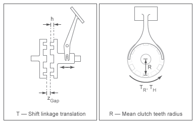
Moving the ring toward the hub so that the teeth interlock changes the clutch state to engaged. Tooth overlap must exceed a minimum value for engagement. Moving the ring in reverse so that the two sets of teeth no longer interlock changes the clutch state back to disengaged. Port S specifies the shift linkage position. When the clutch is fully disengaged, the shift linkage position is zero. When the clutch is fully engaged, the shift linkage position equals the sum of the tooth height and the ring-hub clearance of the fully disengaged state,
where:
z is the shift linkage position.
h is the tooth height.
zGap is the ring hub clearance when disengaged.
The figure shows side and front views of the dog clutch and some of its relevant variables.
Torque Transmission Models
You can choose from these torque transmission models.
To simulate an abstracted dog clutch, set Torque transmission model to Two-mode. The two-mode torque transmission model uses mode charts to control whether the clutch is engaged or disengaged. You can control the shift linkage position using logic-based commands or a linkage position physical signal. When you use logic-based commands, false at port X represents a disengaged clutch, and true represents an engaged clutch.
When you set Torque transmission model to Friction clutch approximation - Suitable for HIL and, the block treats the clutch engagement as a friction phenomenon between the ring and the hub. This setting is better suited for linearization, fixed-step simulation, and hardware-in-loop (HIL) simulation. The block uses a composite implementation of the Fundamental Friction Clutch block.
When you use this setting, the clutch has three possible configurations: disengaged, engaged, and locked. When disengaged, the contact force between the ring and the hub is zero. This force remains zero until the shift linkage reaches the minimum position for engagement.
When the ring-hub tooth overlap, h, exceeds the minimum value for engagement, the contact force between the two components begins to increase linearly with the shift linkage position, z.
At full engagement, the contact force reaches its maximum value and the clutch state switches to locked. In this state, the ring and the hub spin as a unit without slip. To unlock the clutch, the transmitted torque must exceed the value of the Maximum transmitted torque parameter.
When you set Torque transmission model to Dynamic with backlash, the block simulates clutch phenomena such as backlash, torsional compliance, and contact forces between ring and hub teeth. This model provides greater accuracy than the friction clutch approximation.
When you use this setting, the clutch has two possible configurations: disengaged and engaged. When disengaged, the contact force between the ring and the hub is zero. This force remains zero until the shift linkage reaches the minimum position for engagement.
When the ring-hub tooth overlap, h, exceeds the engagement threshold value, the clutch transmits torque. This torque is the sum of torsional spring and damper components, including backlash between the ring and hub teeth, such thatwhere:
kRH is the torsional stiffness of the ring-hub coupling.
ϕ is the relative angle, about the common rotation axis, between the ring and the hub.
δ is the backlash between ring and hub teeth.
ω is the relative angular velocity between the ring and the hub. This variable describes how fast the two components slip past each other.
Compliant end stops limit the translational motion of the clutch shift linkage and the ring. The compliance model treats the end stops as linear spring-damper sets. The location of the end stops depends on the relative angle and angular velocity between the ring and hub teeth:
If the teeth align and the relative angular velocity is smaller than the maximum value for clutch engagement, the end stop location is the sum of the ring-hub clearance when fully disengaged and the tooth height. The clutch can engage in this end stop position.
If the teeth do not align or the relative angular velocity exceeds the maximum value for clutch engagement, the end-stop location is set to prevent the ring from engaging the hub. The clutch does not engage in this end stop position.
Translational friction opposes shift linkage and ring motion. This friction is the sum of Coulomb and viscous components, such thatwhere:
FZ is the net translational friction force acting on the shift linkage and ring.
kK is the kinetic friction coefficient between ring and hub teeth.
FN is the normal force between ring and hub teeth, where FN = TC/Rm.
v is the translational velocity of the shift linkage and the ring.
vth is the translational velocity threshold. Below this threshold, a hyperbolic tangent function smooths the Coulomb friction force to zero as the shift linkage and ring velocity tends to zero.
μT is the viscous damping coefficient acting on the shift linkage and the ring.
When you set Torque transmission model to Dynamic
modal, the block determines the discrete clutch modal behavior by
taking the shift linkage position from the mechanical translational conserving port
S. This setting captures more complex clutch dynamics than the
Two-mode parameterization and is faster than the
Friction clutch approximation and Dynamic
with backlash settings.
You can use the Dynamic modal setting to simulate
engagement blocking when the speed difference is too large for the clutch plates to
engage. The block represents engagement blocking as a spring-damper system where you can
parameterize the spring and damping coefficients. The engagement modes overlap, which
prevents the mode from changing until the shift linkage position is beyond the
engagement overlap region. You define the engagement overlap region using the
Tooth overlap to engage parameter.
The linkage position constrains are:
z is the shift linkage position at port S.
h is the Tooth height parameter.
zGap is the Ring hub clearance when disengaged parameter.
zOverlap is the Tooth overlap to engage parameter.
ωthr is the Engagement speed threshold parameter.
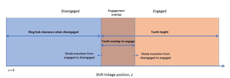
The engagement mode positions are:
z = 0 — The clutch is fully disengaged.
0 < z < zGap — The clutch is disengaged when the shift linkage position is in the region defined by zGap. The clutch can transition from disengaged to engaged at x = zGap + zOverlap.
zGap < z < h — The clutch is engaged when z is in the region defined by h. The clutch can transition from engaged to disengaged when z = zGap.
z = zGap + h — The clutch is fully engaged.
z = zGap + zOverlap — When z is in the engagement overlap region, the clutch engages only when the speed difference is less than the value of the ωthr parameter.
Rotational Power Dissipation
When the clutch slips under an applied torque, it dissipates power. The power loss equals the product of the slip angular velocity and the contact torque between the ring and the hub, such that
where:
Ploss is the dissipated power due to slipping.
TC is the kinetic contact torque.
Thermal Modeling
When you set Torque transmission model to
Friction clutch approximation - Suitable for HIL and
linearization, you can model the effects of heat flow and
temperature change by using the optional thermal conserving port,
T.
Linearization
To optimize your model for linearization, use the Clutch > Torque transmission model parameter default setting, Friction clutch approximation -
Suitable for HIL and linearization.
Hardware-in-the-Loop Simulation
For optimal simulation performance, use the Clutch > Torque transmission model parameter default setting, Friction clutch approximation -
Suitable for HIL and linearization.

Ports
Input
Output
Conserving
Parameters
Extended Capabilities
Version History
Introduced in R2011aYou can also select a web site from the following list:
Americas
- América Latina (Español)
- Canada (English)
- United States (English)
Europe
- Belgium (English)
- Denmark (English)
- Deutschland (Deutsch)
- España (Español)
- Finland (English)
- France (Français)
- Ireland (English)
- Italia (Italiano)
- Luxembourg (English)
- Netherlands (English)
- Norway (English)
- Österreich (Deutsch)
- Portugal (English)
- Sweden (English)
- Switzerland
- United Kingdom (English)